
After becoming familiar with building and flying my first 5” quad, and experimenting with a ready-to-fly (RTF) micro-quad, I realized what features I was looking for in a drone. First, as a beginner in the hobby I was not aware of how powerful a 5” quad weighting ~600g at 4S was. These quads need wide open spaces and careful flying. They are also very noisy and dangerous if not handled properly. On the other hand, the 2S RTF micro-quad lacked stability, quality of video feed and range, and batteries lasted only a couple of minutes.
As a consequence, I wanted my next build to have the following features: <100g dry weight and <4S voltage for more safety and less noise, >5min fly time per battery, HD camera on-board, reasonable FPV analog video feed and >200m range. I also did not want to sacrifice too much maneuverability and speed, and I wanted to build it myself.
I found that the recent proposal by KababFPV, the Toothpick 3 (TP3), could fulfill all these requirements. It is also probably the most optimized non-professional micro-drone that can be built with off-the-shelf components, after lots of tests by the author. Because the original proposal lacked an HD camera, I decided to sacrifice some grams and add a split-type camera. I calculated that should add 7g to the build (~7% of the total weight).
The most unparalleled features of the TP3 are its optimized frame and the very efficient brushless motors. The frame features 2.5mm arms and 1.5mm body plates with T700 carbon fiber. First thing I did upon receipt was to chamfer the edges with a file and to thoroughly wash all the carbon fiber parts in soap water. Although the vendor is trustworthy and the parts came flawless, I got this habit from Oscar Liang. It is always good to go through this process with your new builds to avoid sharp edges and remove all the carbon dust.

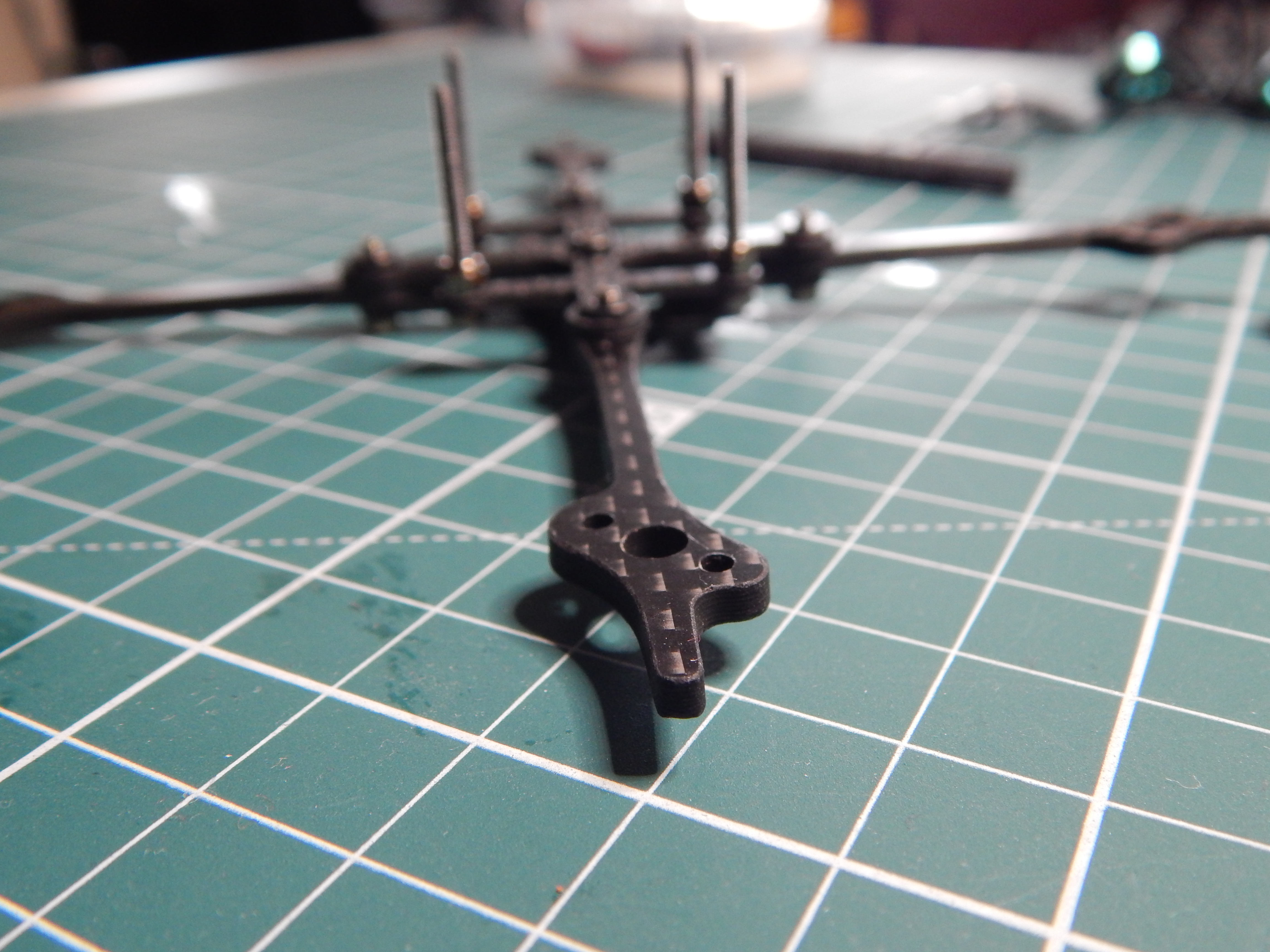
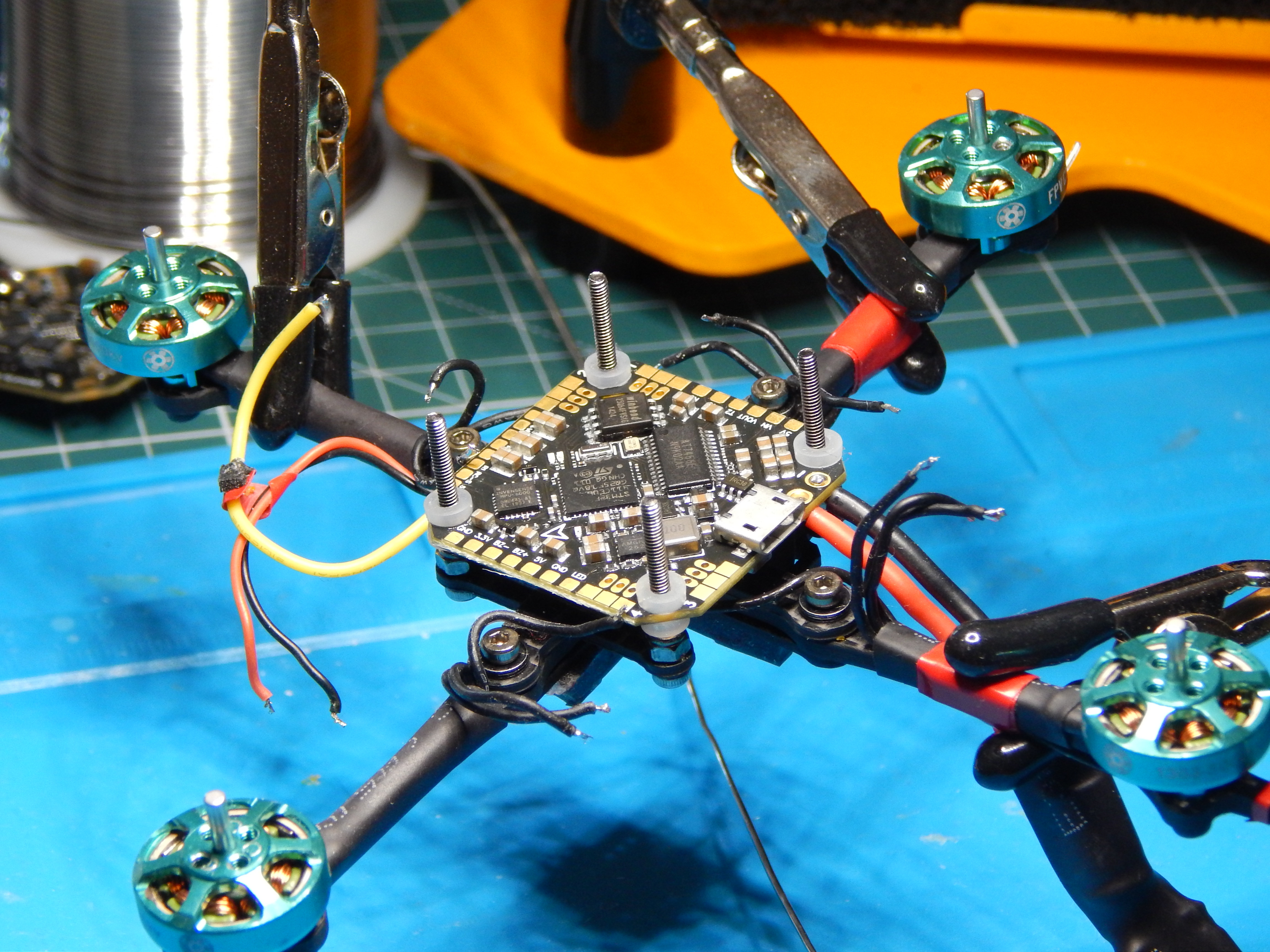
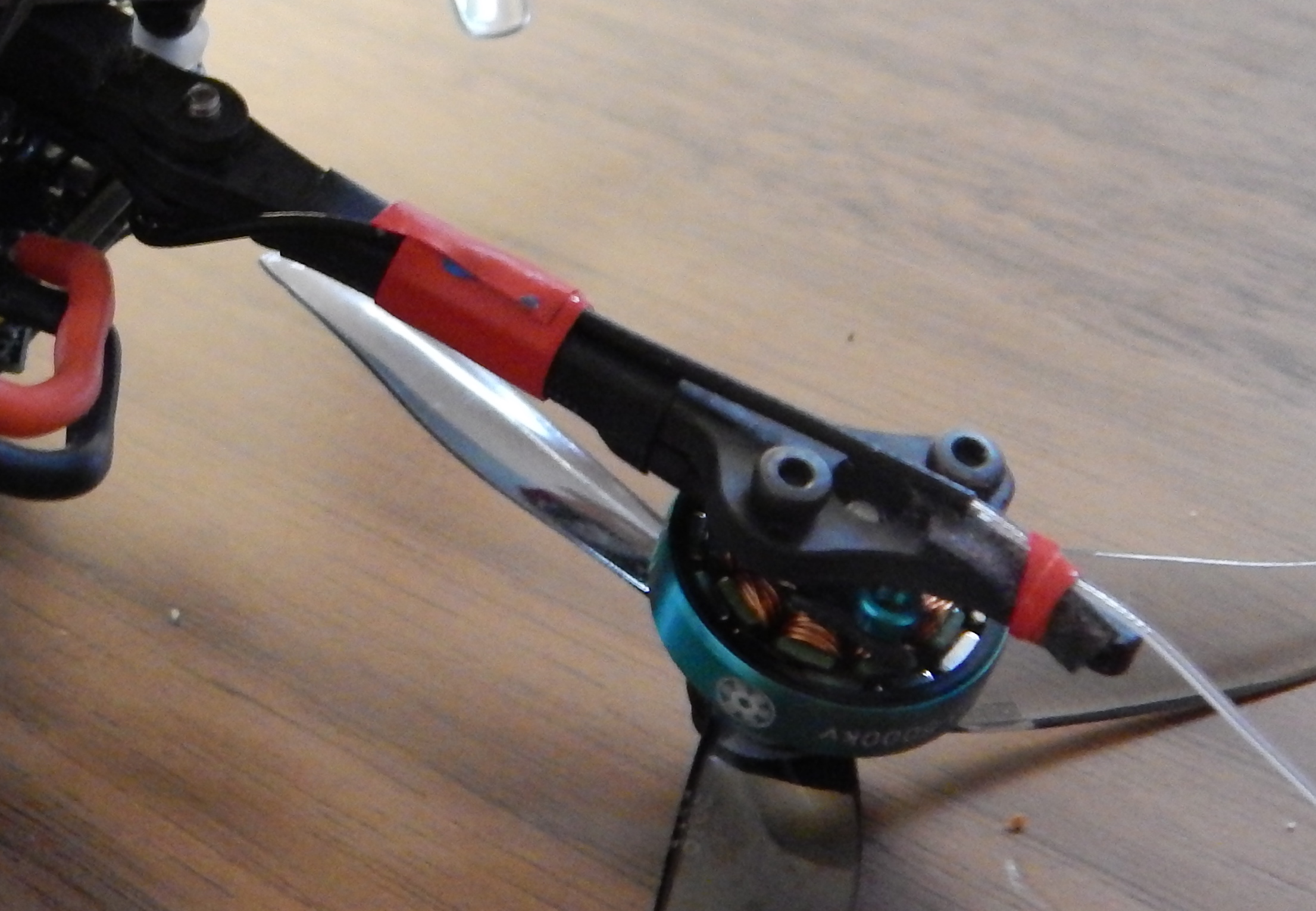
The unique 1303 size for the motors at 5000kV with 2mm shaft was demonstrated by KababFPV to give great performance at low weight (~6g/motor). After screwing each motor to the arms, I used heat shrink tubing for protection (and well, for elegance). Lacking a proper heat gun at home, I used a hair dryer for the tubing, which ended up being sufficient for this application.


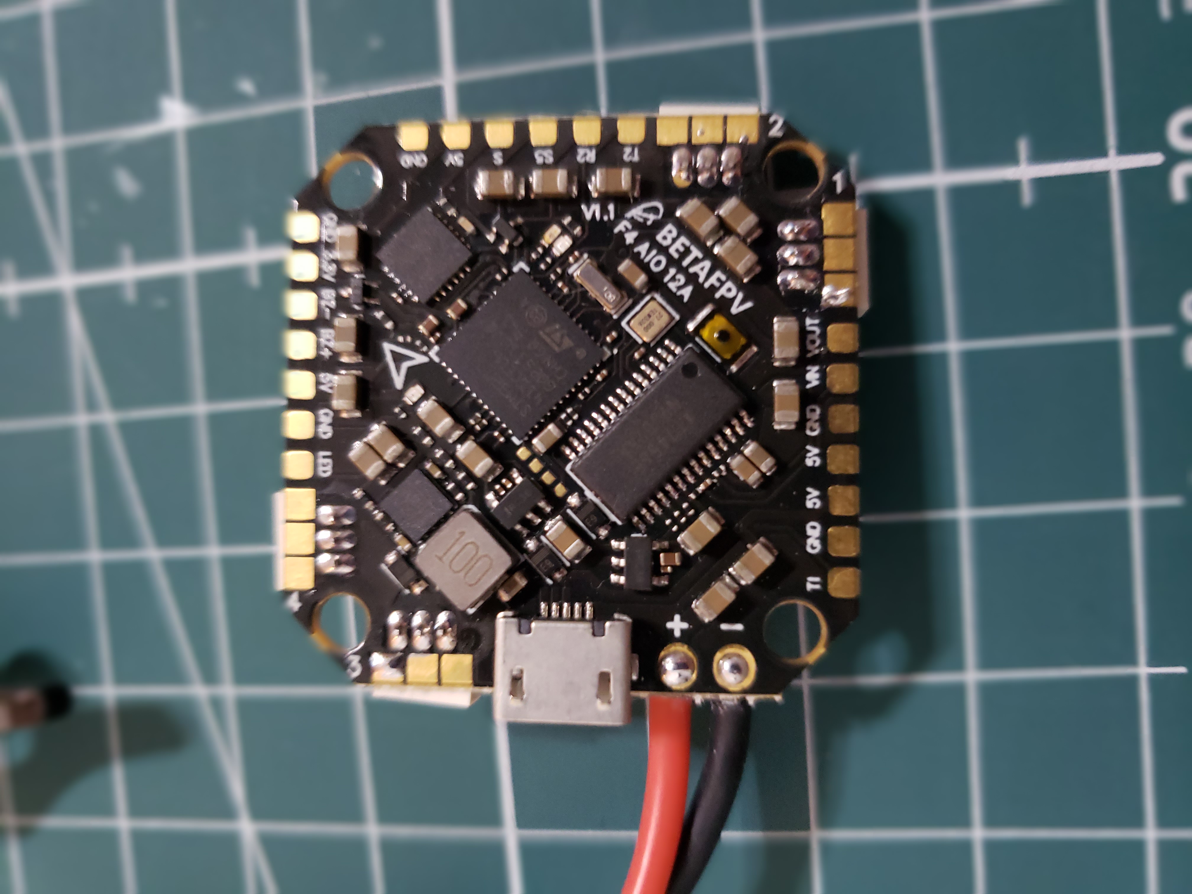
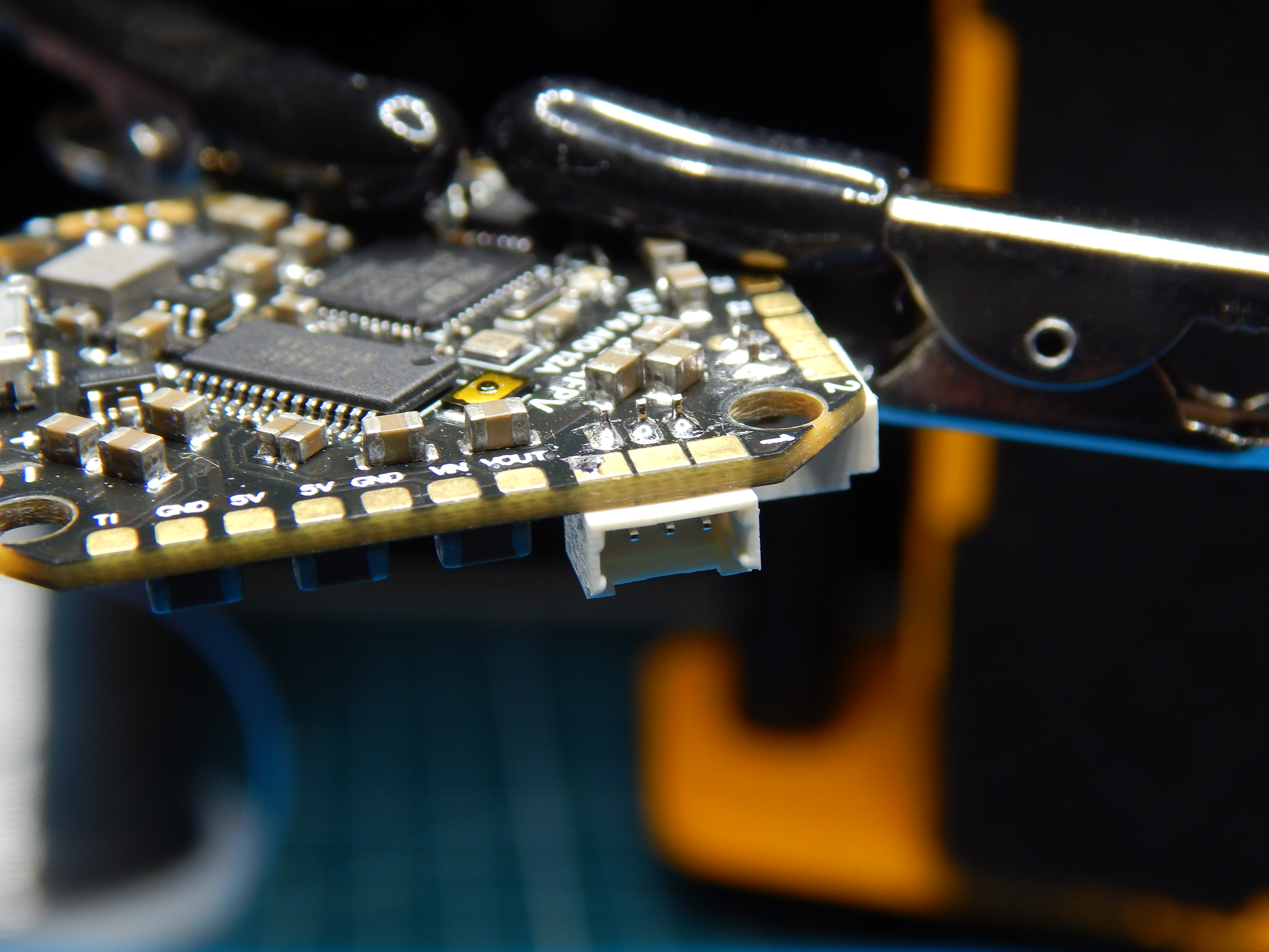
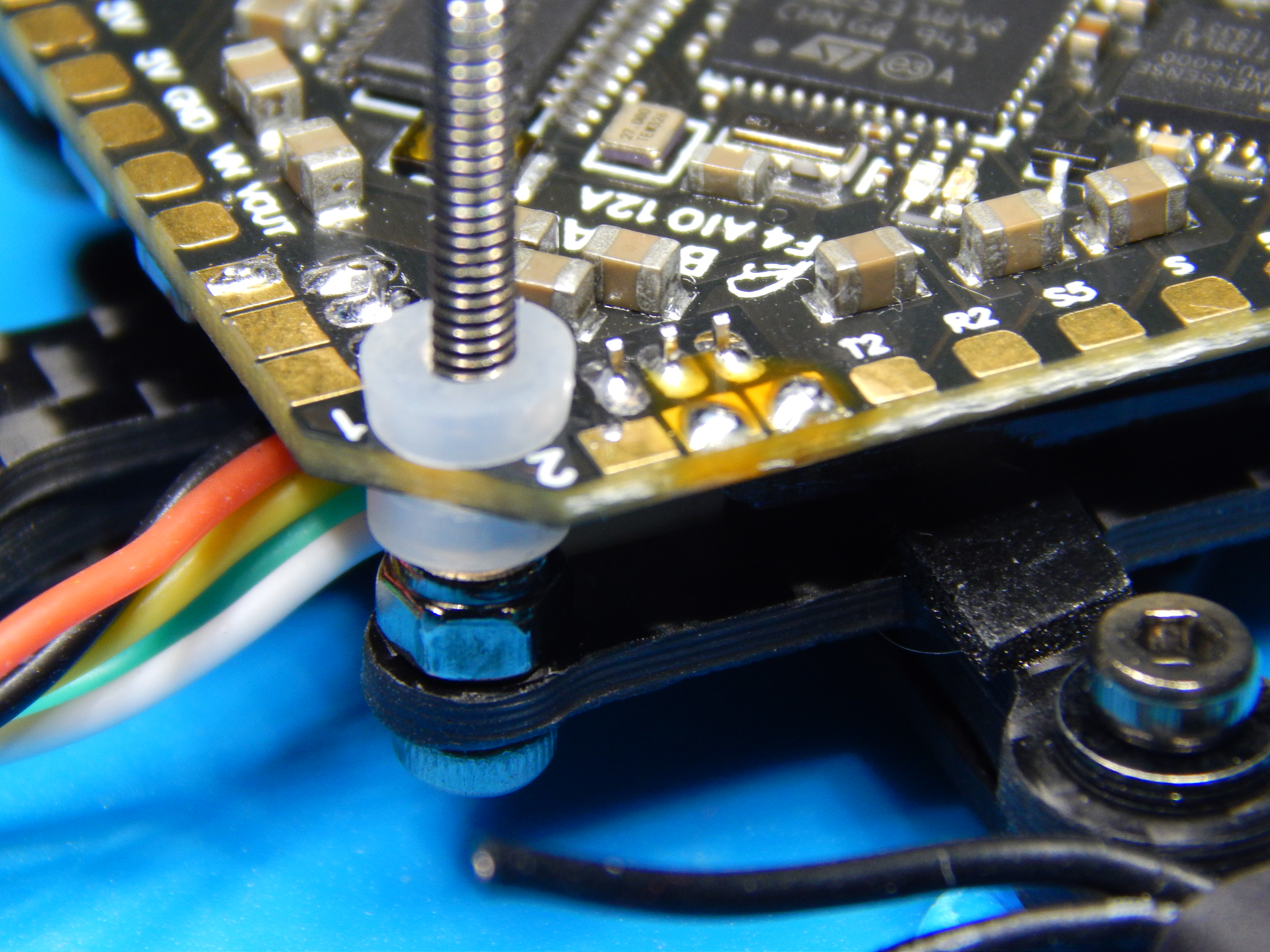
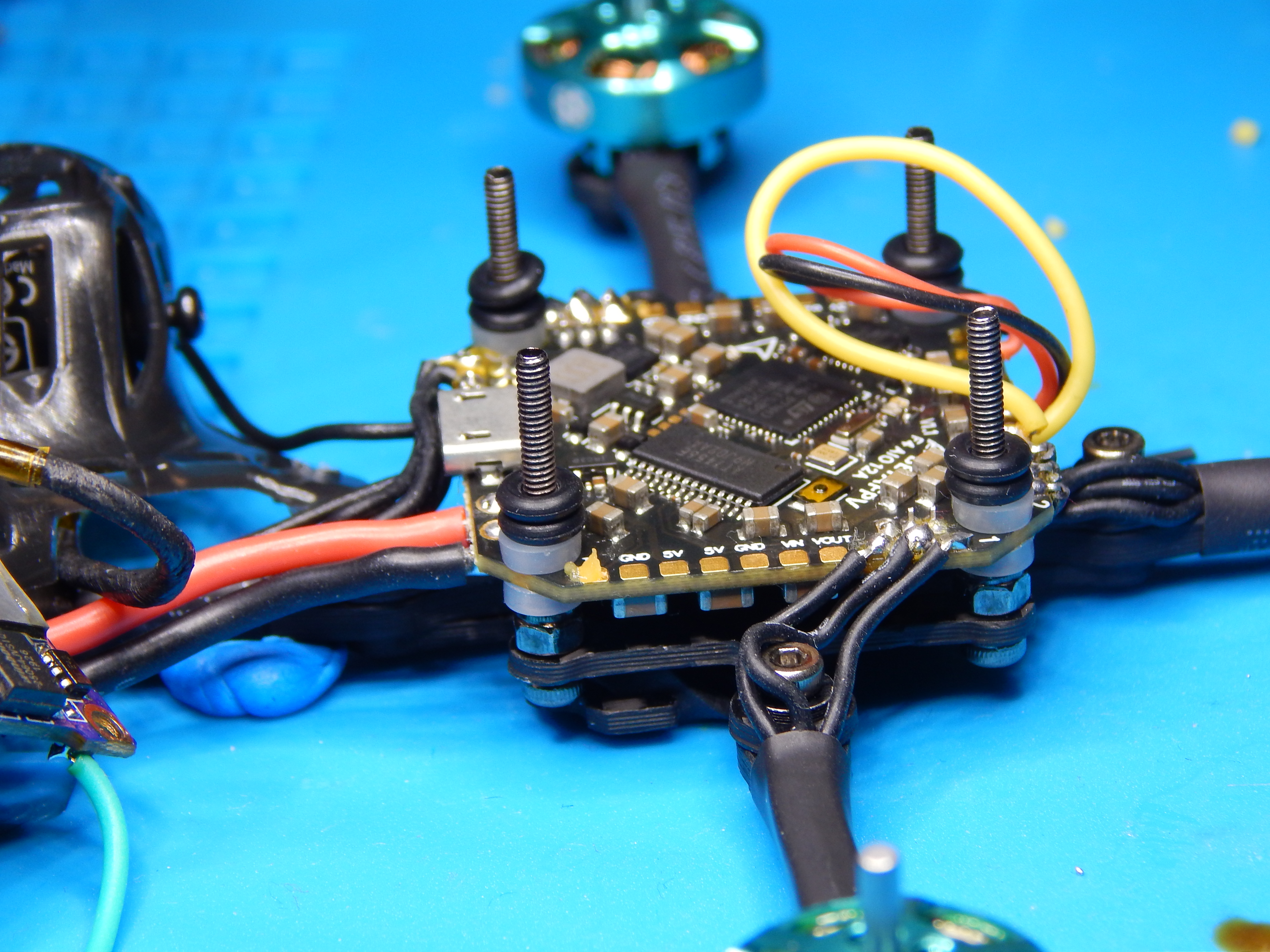
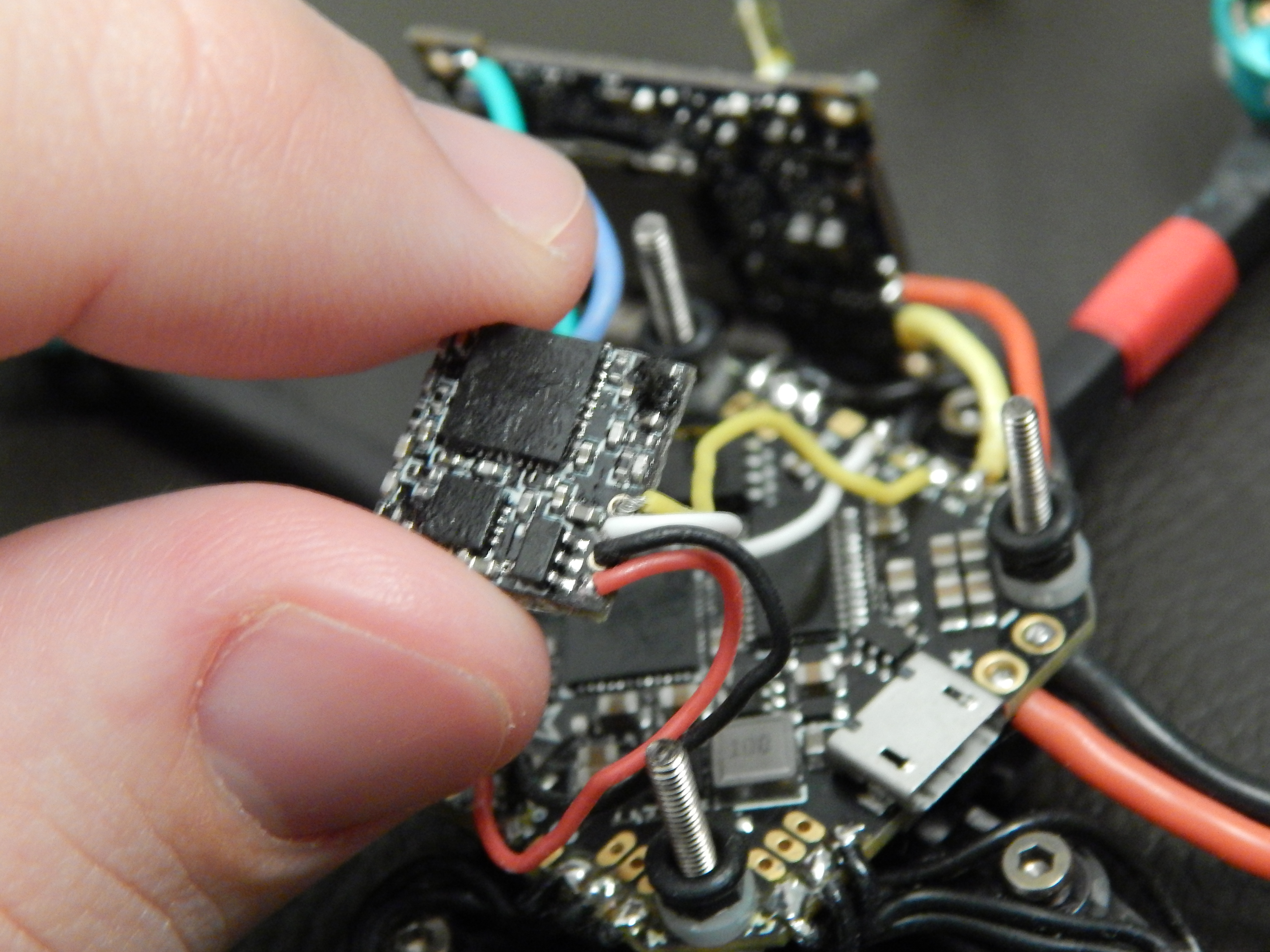
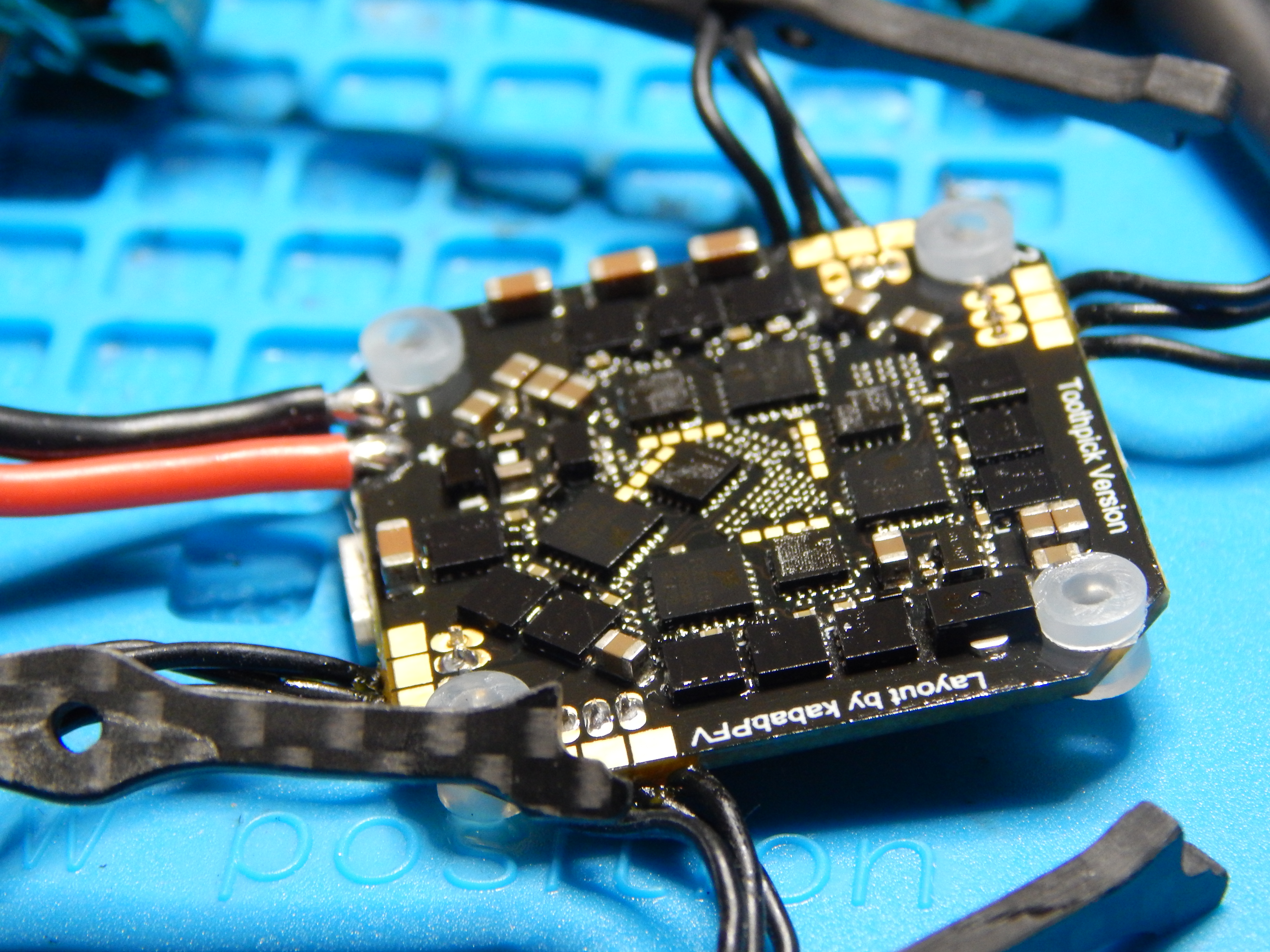
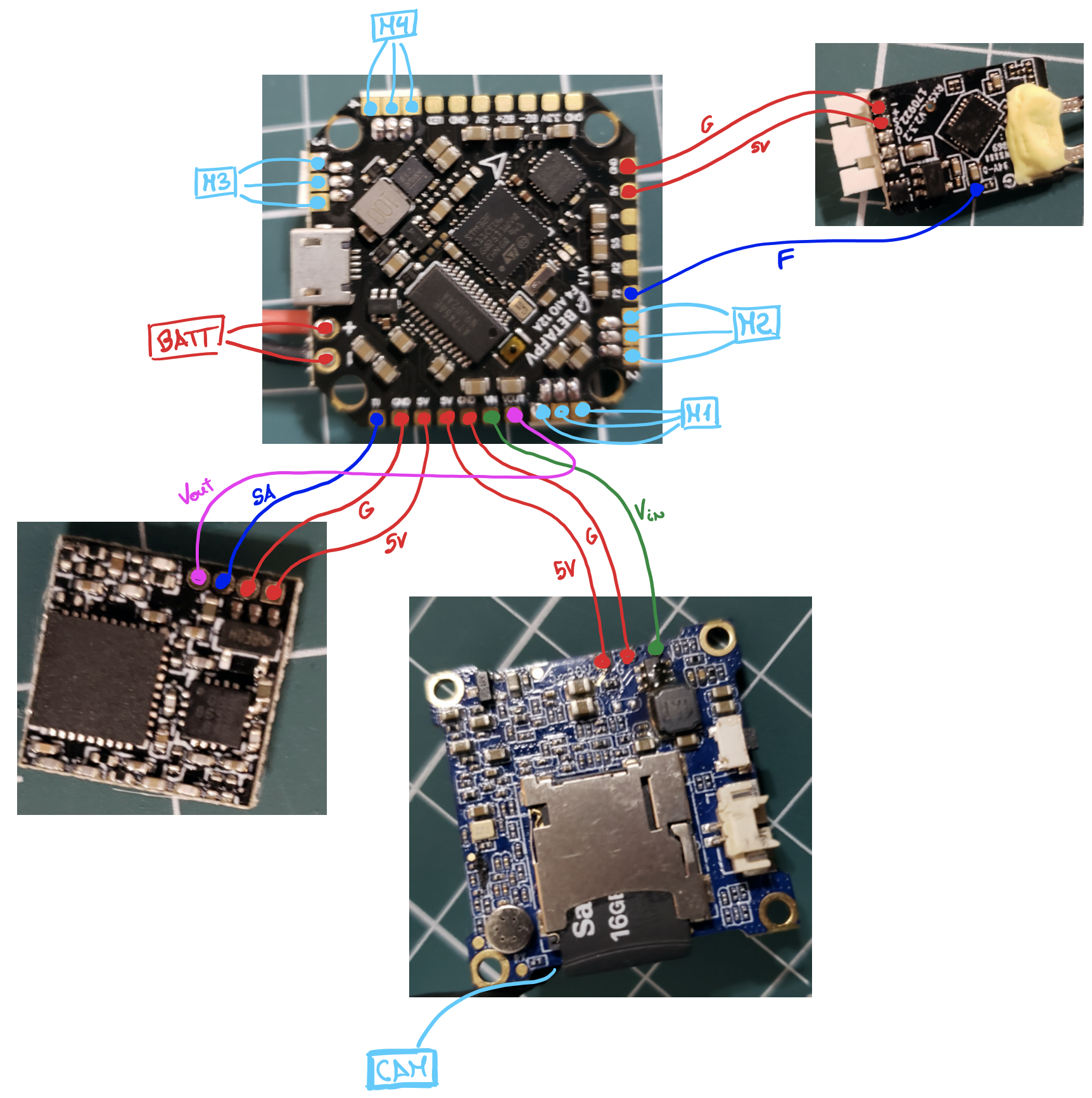
For the flight controller (FC) I used the BetaFPV AIO board. AIO stands for all-in-one, i.e. in a single board you have the flight controller, the power distribution system (PDB) and the electronic speed controllers (ESC) for the brushless motors. I would have liked to have separate ESCs (as in my 5”), because when any component breaks in these AIOs, the entire board has to be replaced (not cheap). However, there is not much diversity for components of this size, and most, if not all, micro dones have AIO boards. This BetaFPV features a standard F411 processor and has a 26.5mm mounting pattern, matching the frame (standard “whoop” size). It has a MPU6000 motion processing unit (gyroscope+accelerometer) and a low-ESR capacitor already soldered in. It came also with pin connectors soldered in, but I preferred to de-solder them to reduce weight and solder motors directly to the board.

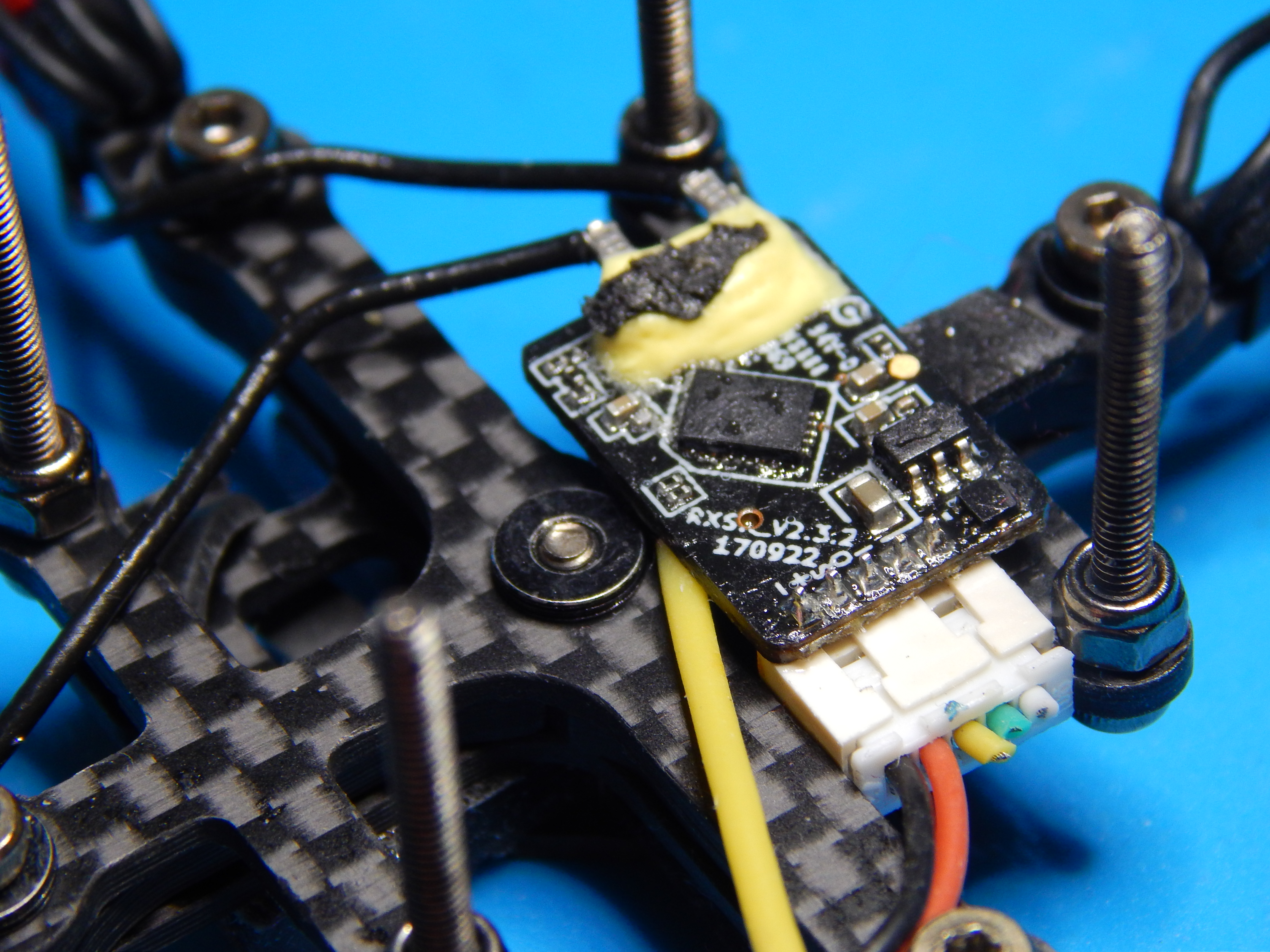
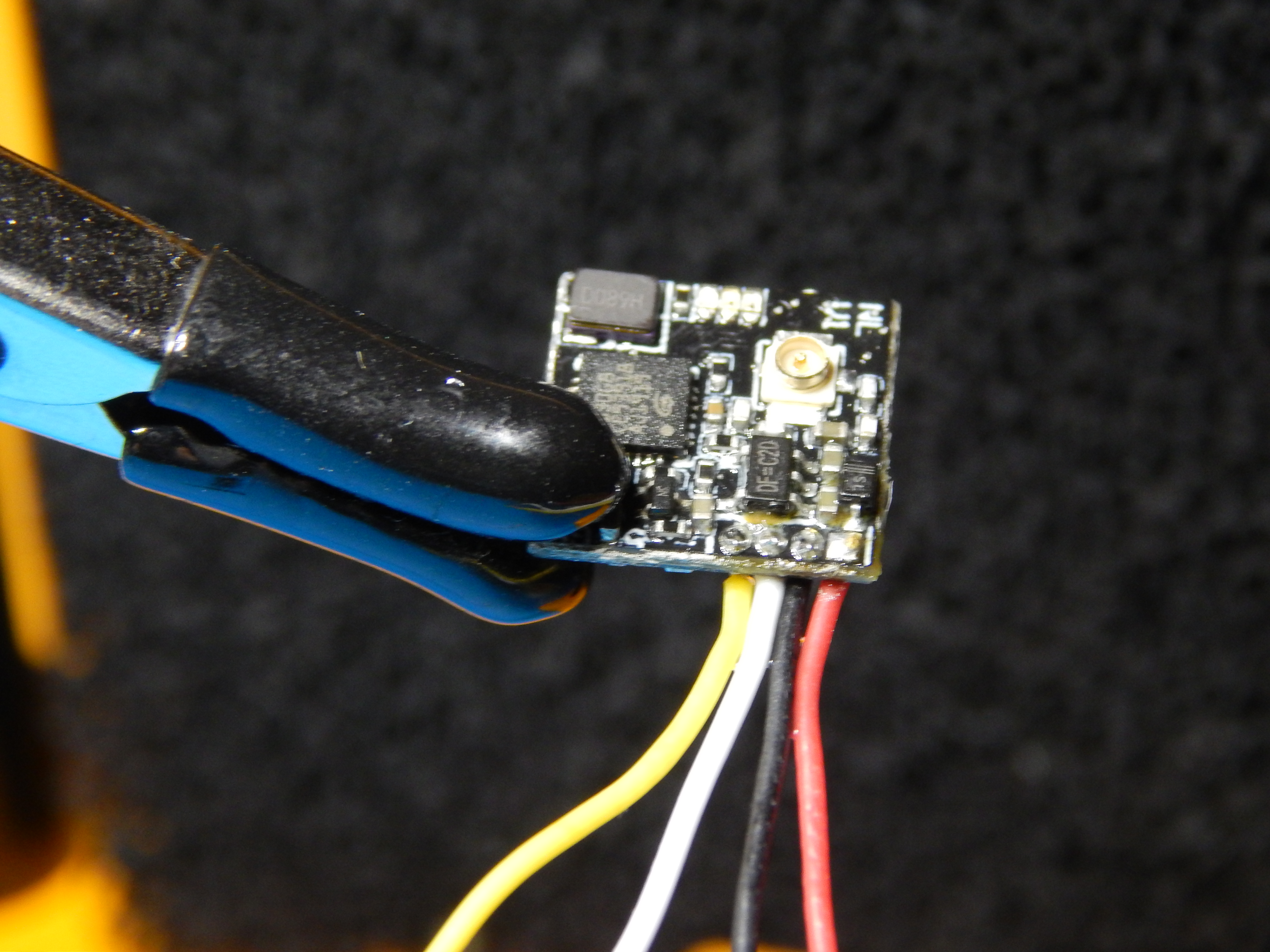
Because I do not need to take advantage of the features of Crossfire receivers, I went simple and selected the FrSky R-XSR receiver with SBUS protocol and 16 channels, compatible with my Taranis transmitter. I also found a very neat place below the FC board to put the RX. Because the FC board I selected had very limited UART ports, I had to use the F-port on the R-XSR if I wanted both SBUS and Smartport (lots of telemetry sensors information on the radio!). To do that, I had to solder the wires to the very small pads on the R-XSR. Not the most elegant, but still a functional solution. To reduce weight I cut the three remaining wires pertaining to the separate SBUS/SmartPort and the CPPM.


Next, I added the FC board above a nut and a vibration dampener. This adds stability to the build, and the soft mount helps the readings of the gyroscope by reducing noise from motor vibrations that travel through the carbon fiber. It is time to solder the motor wires to the corresponding pads on the board. I paid no attention whatsoever to the order to solder the wires, because this only affects the spinning direction, which can be easily reversed with the BLHeli firmware.
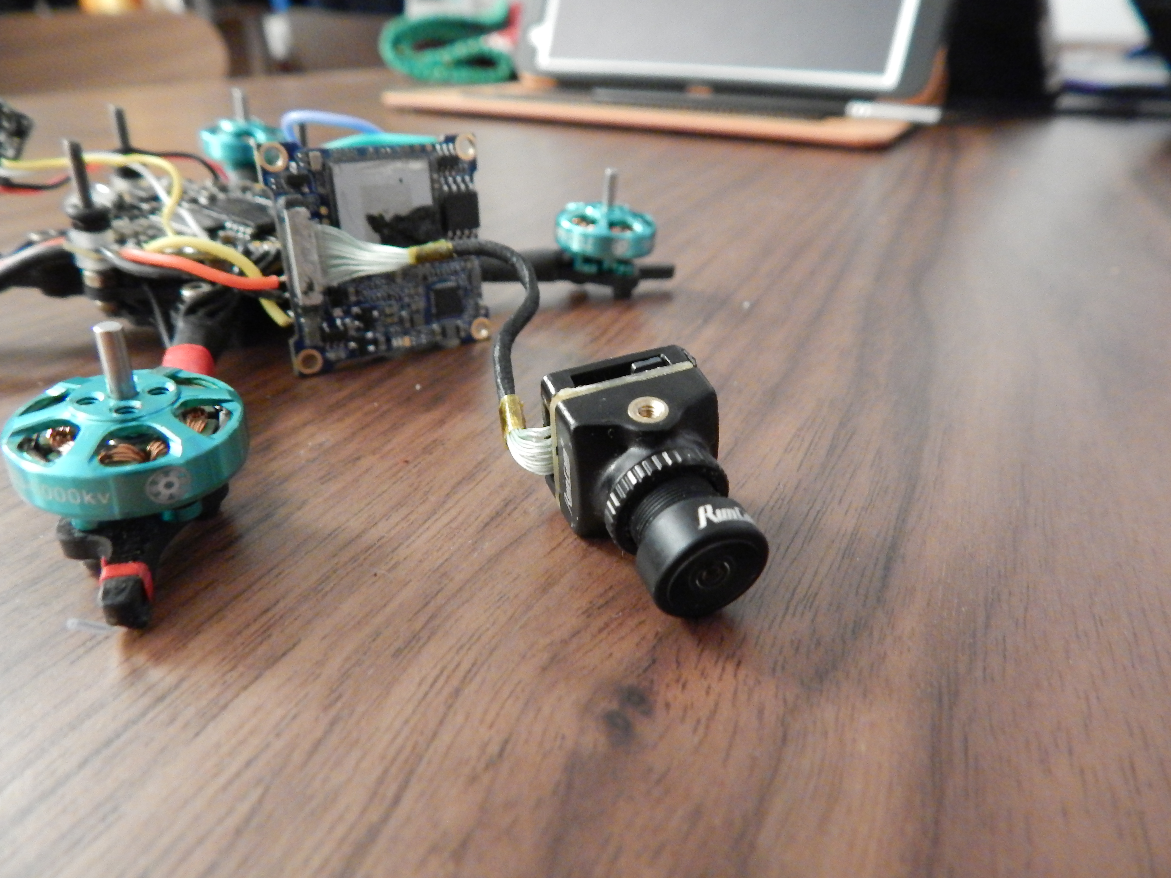
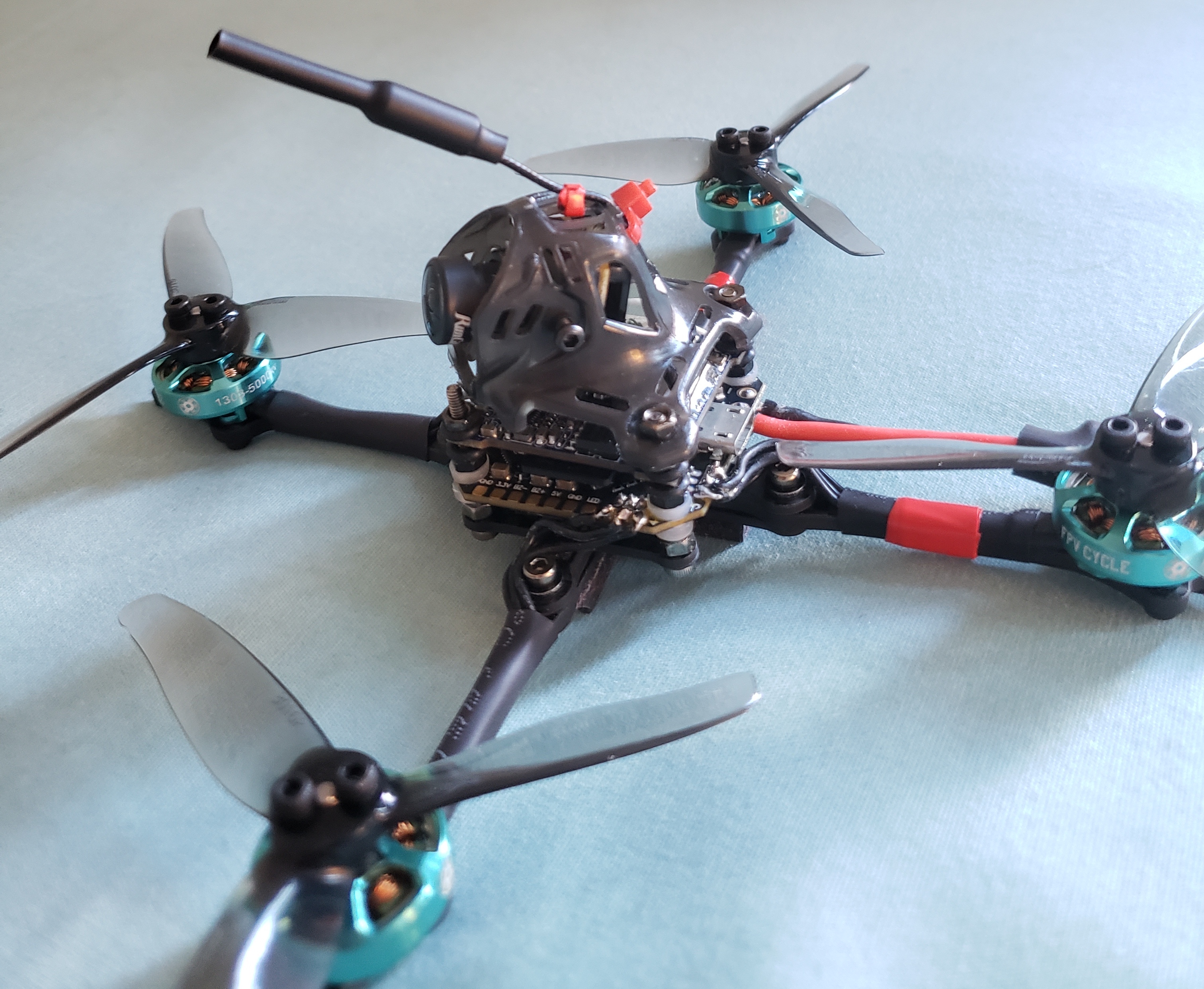
As mentioned earlier, I decided to add an HD camera on-board. In the world of first-person-view (FPV) quads, this typically means that two cameras are on-board: a HD/4K camera to record off-line footage (e.g. a GoPro) and a low-latency analog video camera that sends video to the pilot’s goggles/monitor. In micro-quads like this one, having a GoPro on-board is unfeasible (although this may change soon… check out this new solution by Oscar!). In this build, I decided to use the Runcam split 3 nano whoop camera that I had hanging around from a previous quad. This small camera (10.2g) records video with 1080@60fps, while still providing a reasonable FPV feed (checkout this review by Nick Burns). I added a couple of ring vibration dampeners to add height and avoid short circuits between the Runcam board and the FC.


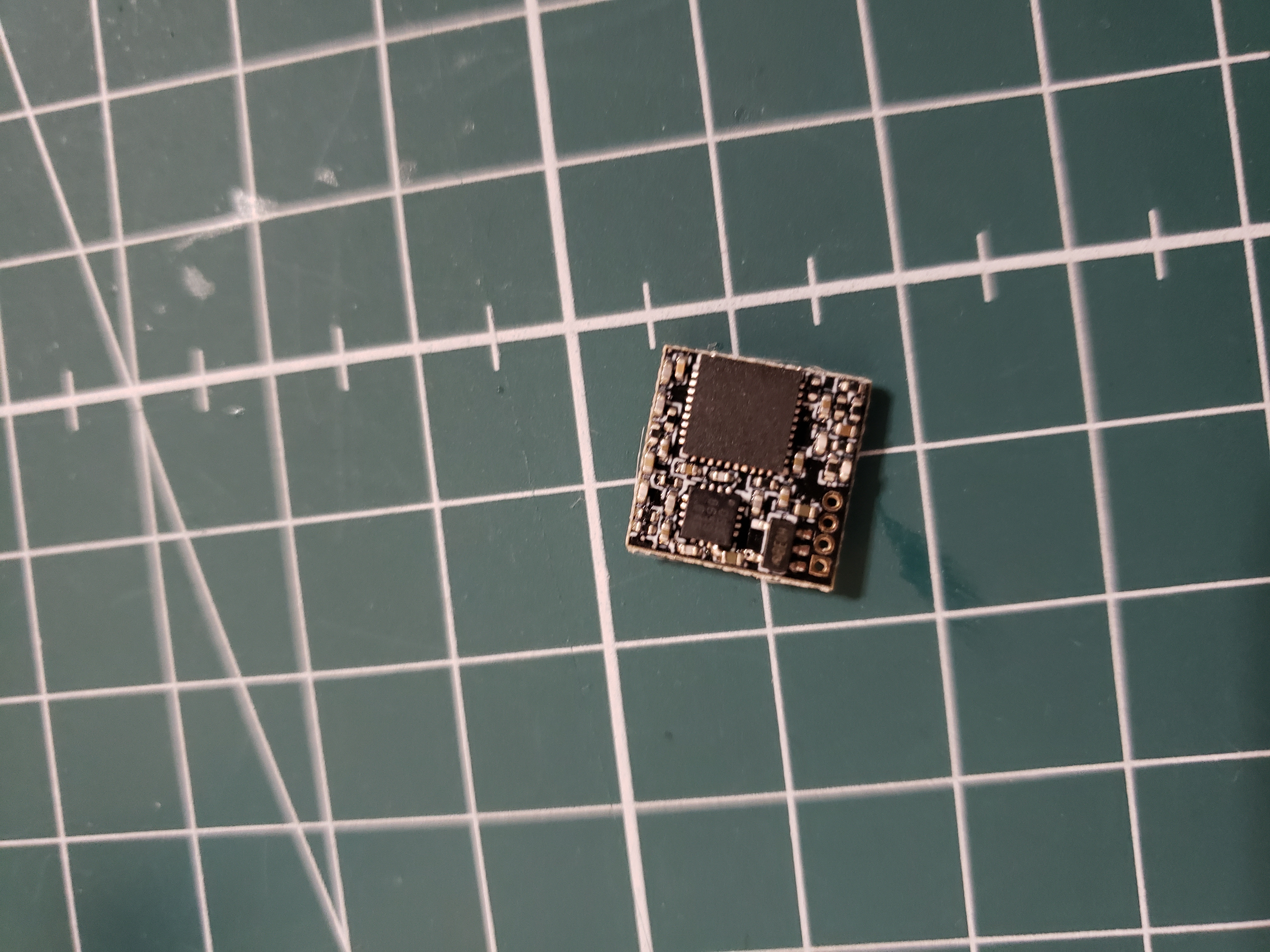
To transmit video to the FPV goggles I use the extremely small and light (1.5g) VTX by NamelessRC. After struggling soldering such small pads, I added it above the Runcam board. To get the on-screen-display (OSD) on the goggles, I run the video-in wire from the Runcam board to the FC and the video-out from the FC to the VTX. This VTX has a U.FL/IPEX connector for the antenna (I am definitely not a fan of this type of connector because of how fragile it is, but at this size and weight it is the only one available). I also added a SmartAudio wire because the VTX is so small it does not have buttons, so to select channels I need to use the IRC Tramp protocol (thus changeable through the OpenTX LUA scripts on the radio or the OSD). Due to lack of more UART ports on the BetaFPV board, I could not add the RX/TX Runcam controllers, but that is an addition I do not quite need at the moment. Adding that connection would let me start/stop recording directly from the radio.
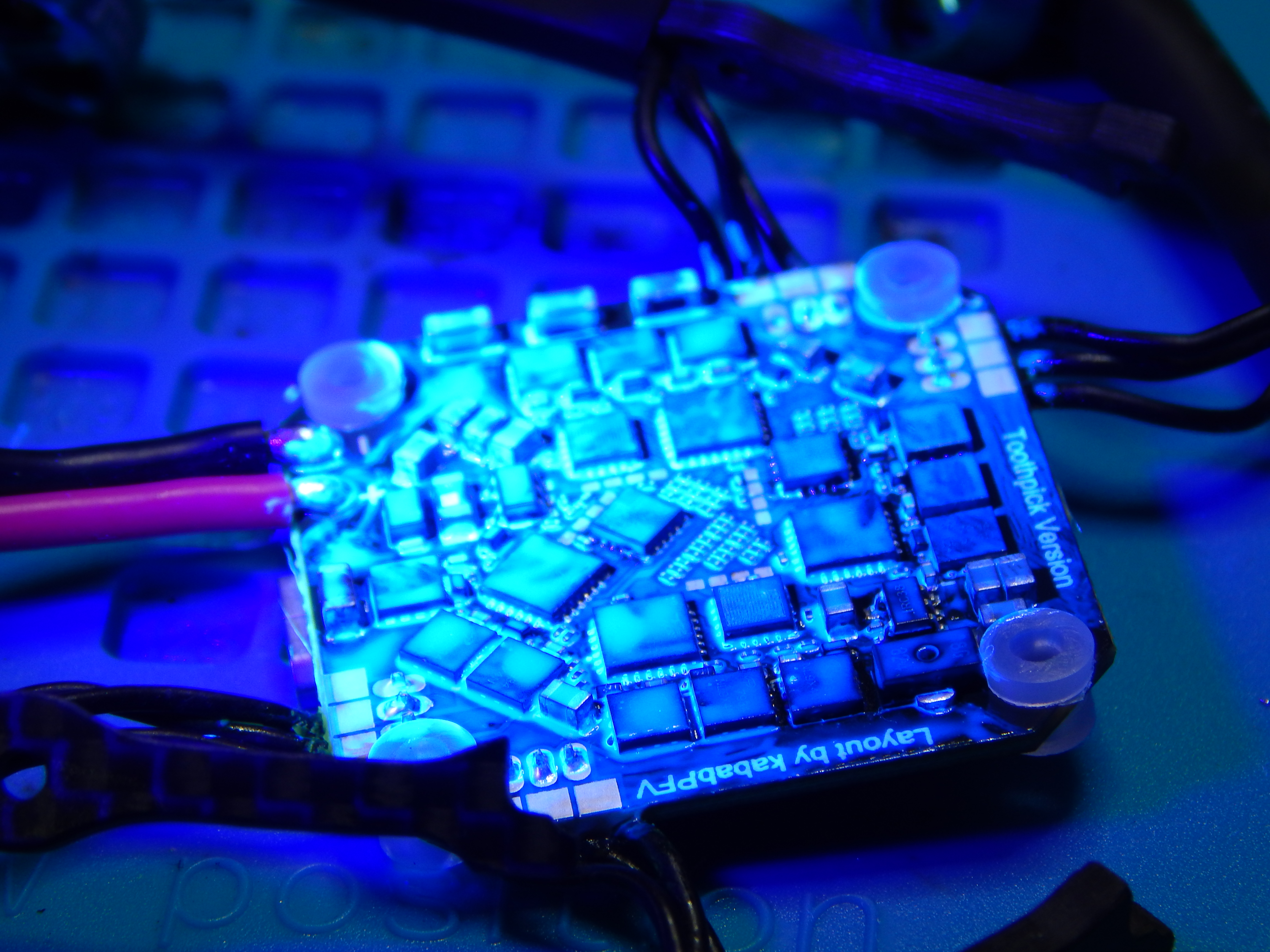
Finally, I decided to cover the entire build with a silicone-modified conformal coating to protect the circuits from corrosion and shorts in humid environments (New England weather…). First the board must be cleaned with 99% isopropyl alcohol and then covered by the conformal coating, which can be detected by UV blacklight!
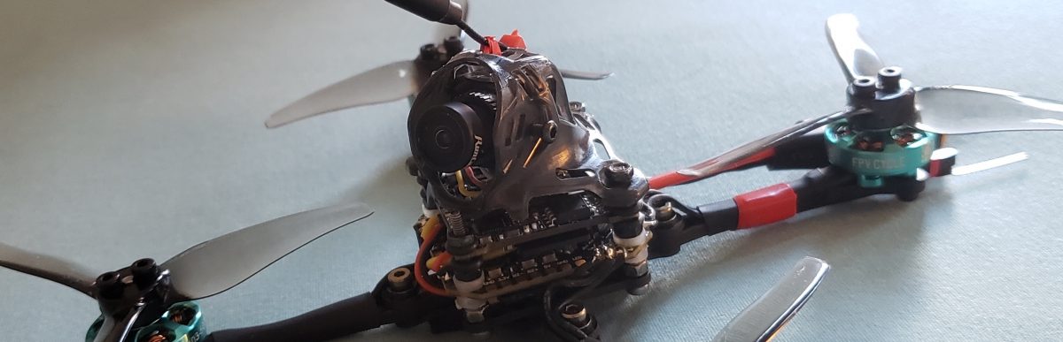
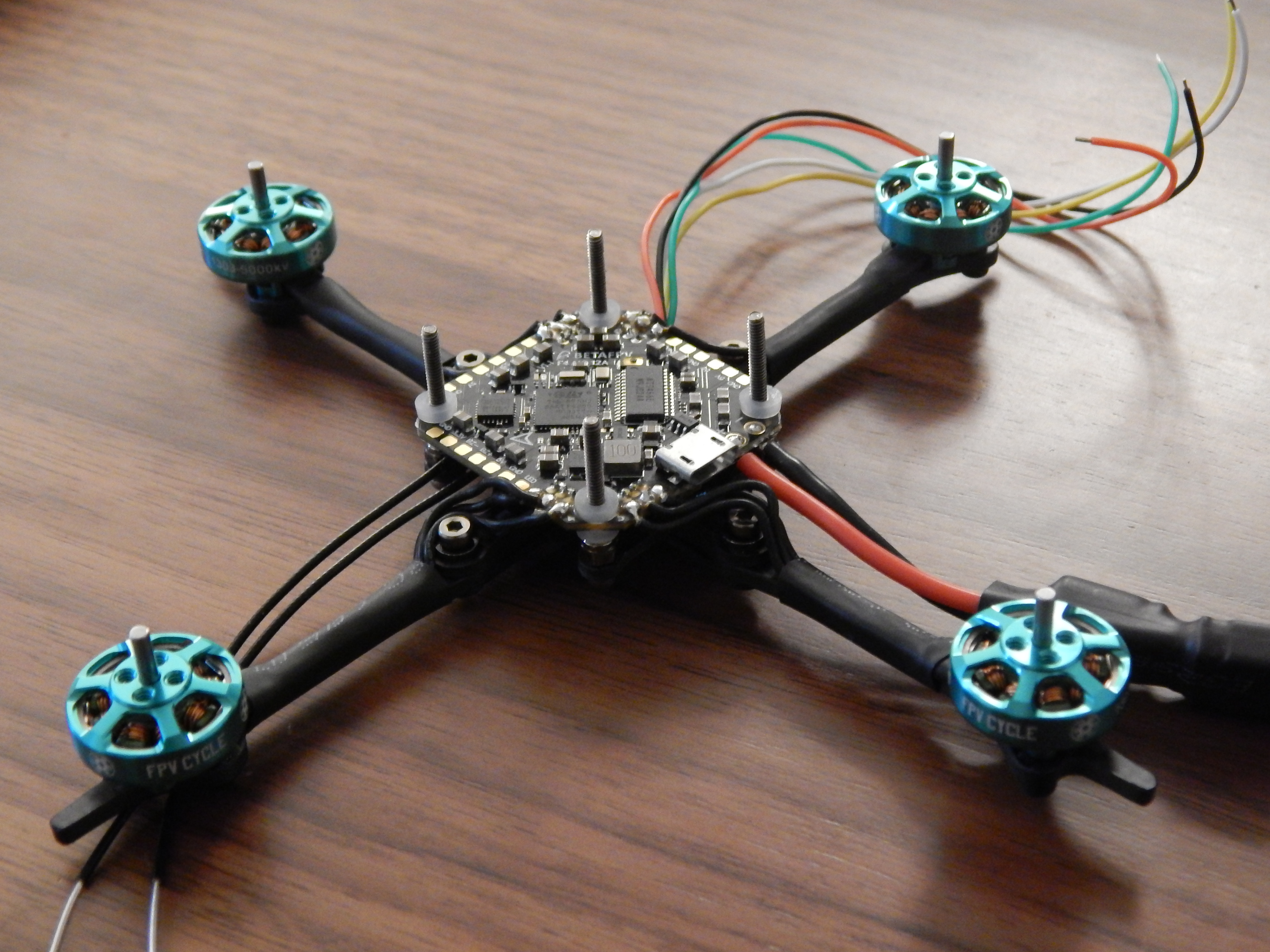
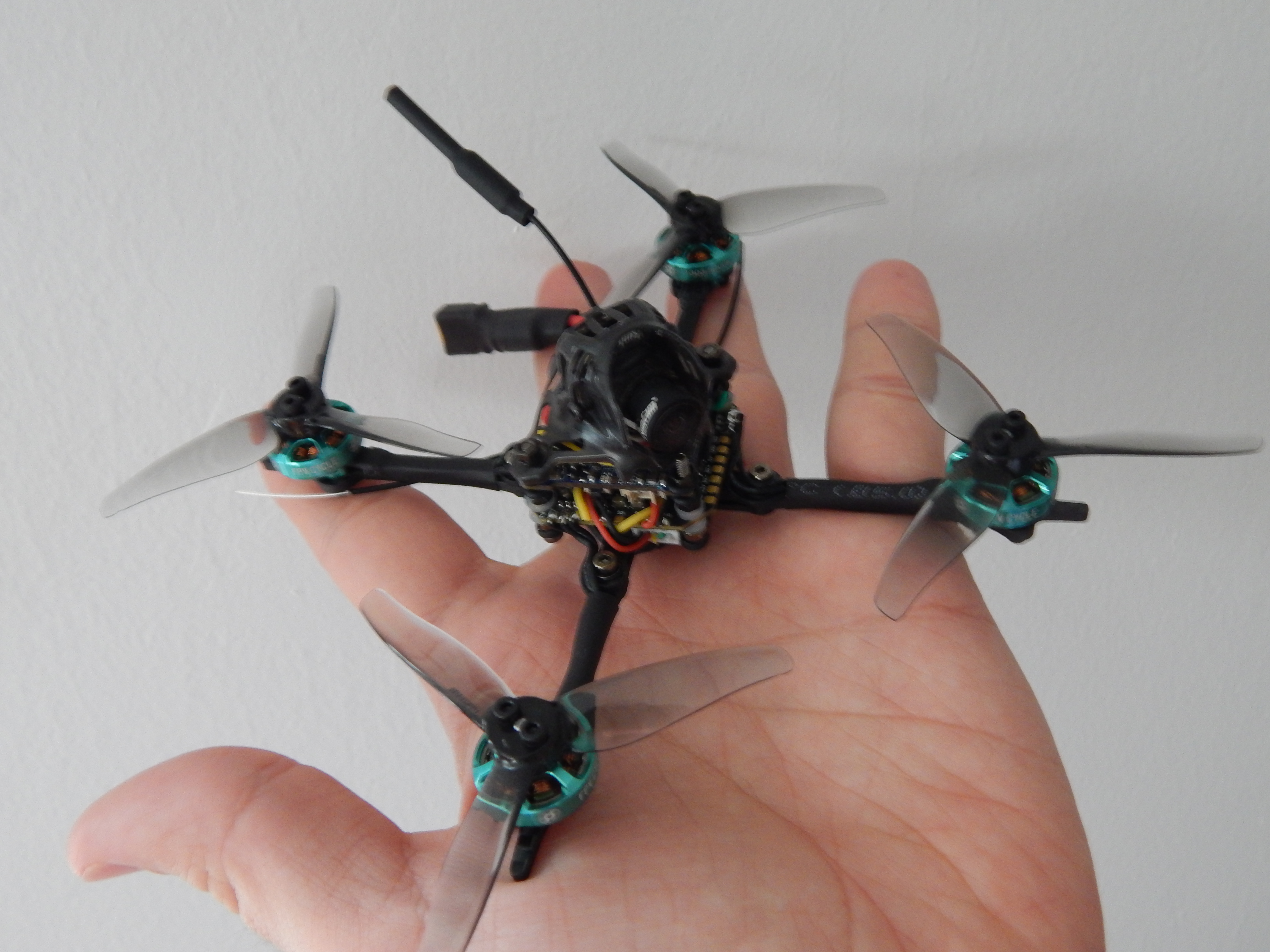
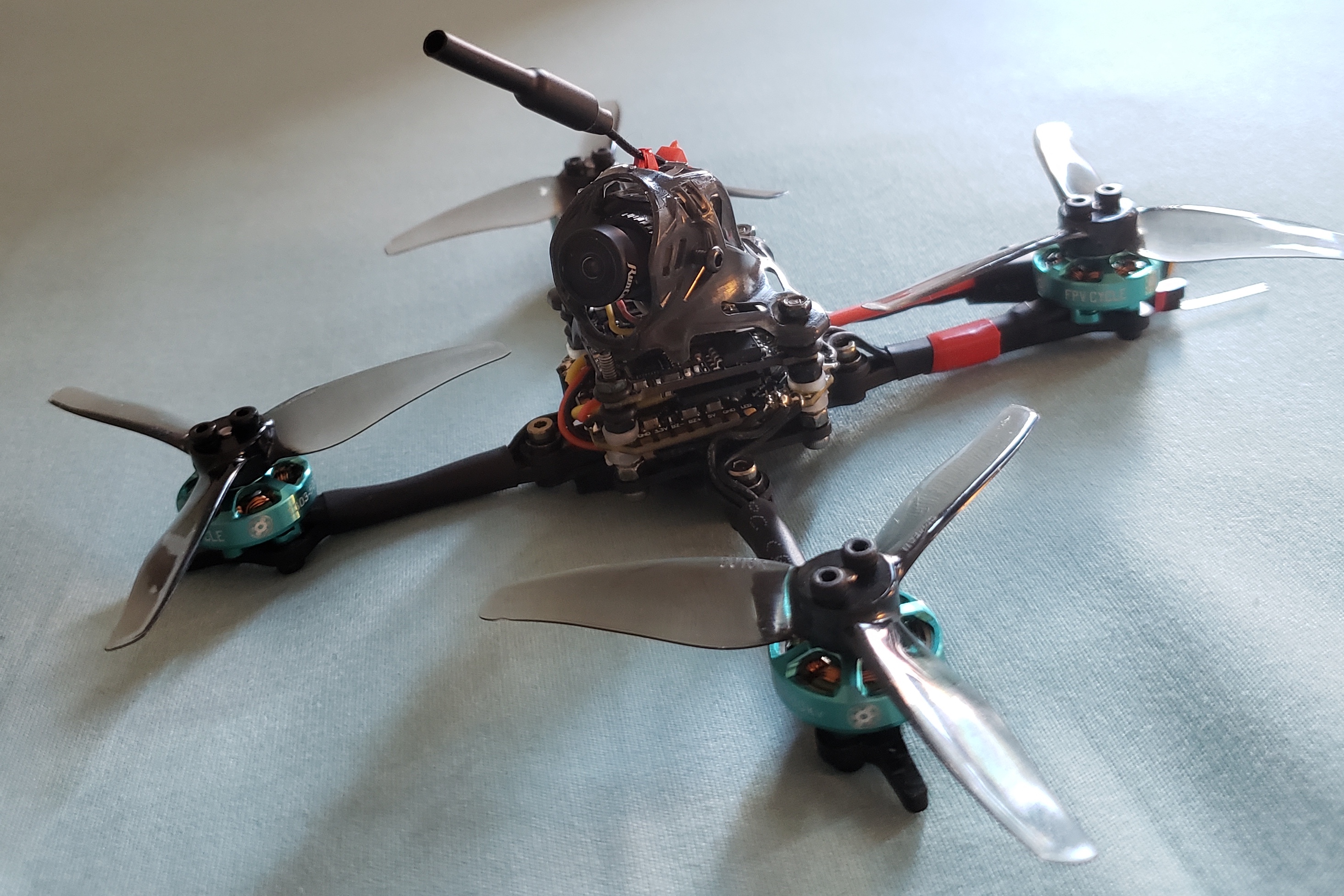
The last step was adding the canopy, blades and the linearly-polarized dipole antennas. For video transmission I use a 5.8GHz antenna, held above the canopy by a couple of zip ties. The RX uses a pair of 2.4GHz antennas for diversity, held by electrical tape at a 90 degrees angle below the rear arms. I think the antennas that come with R-XSR receiver are going to be enough (if I ever want to upgrade for medium to long-range flying, I would switch anyways to Crossfire modules or use lower frequencies). However, I plan to soon install a better VTX antenna; likely an omni-directional circularly-polarized antenna, since I want to fly this quad in parks with a fair amount of trees, so circular polarization will certainly help with multi-pathing. For reference, I have installed in my goggles both a RHCP Lollipop and a directional patch antenna, for diversity. For the propellers, I use 3” tri-blades with 1.6” pitch, as recommended by KababFPV for the choice of motors and battery voltage (3S). On static-load tests this motor-props combination seems to be very efficient (~2gf/W), pulling ~232gf of thrust at full throttle. For the canopy, I am using the one from the HappyModel Larva X. I plan to upgrade this quad with a custom-made 3D printed canopy (that also protects the camera), but this one works for the moment. I use a 3S 450mAh battery below the frame, held by a rubber band. However, I found this to be very unstable, so I also added sticky battery pads with grip to the thin arms.
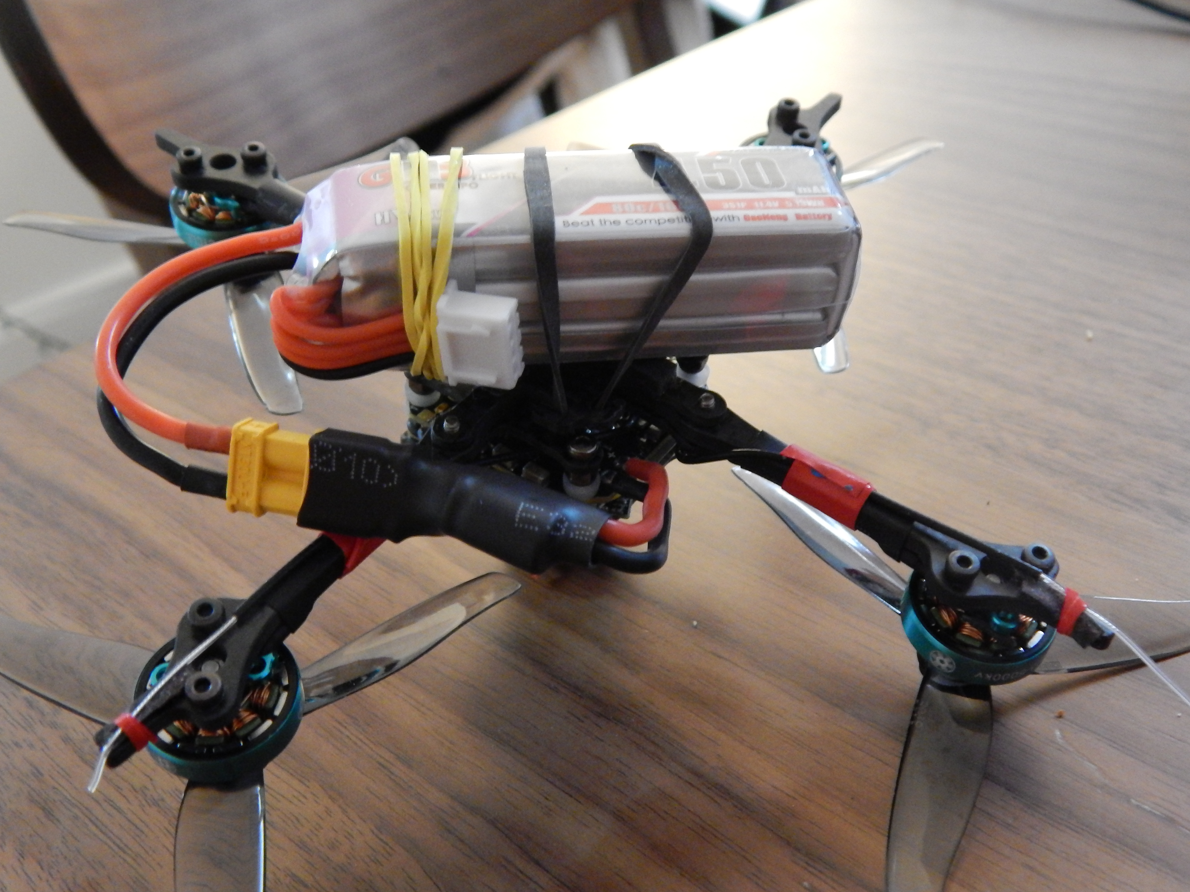
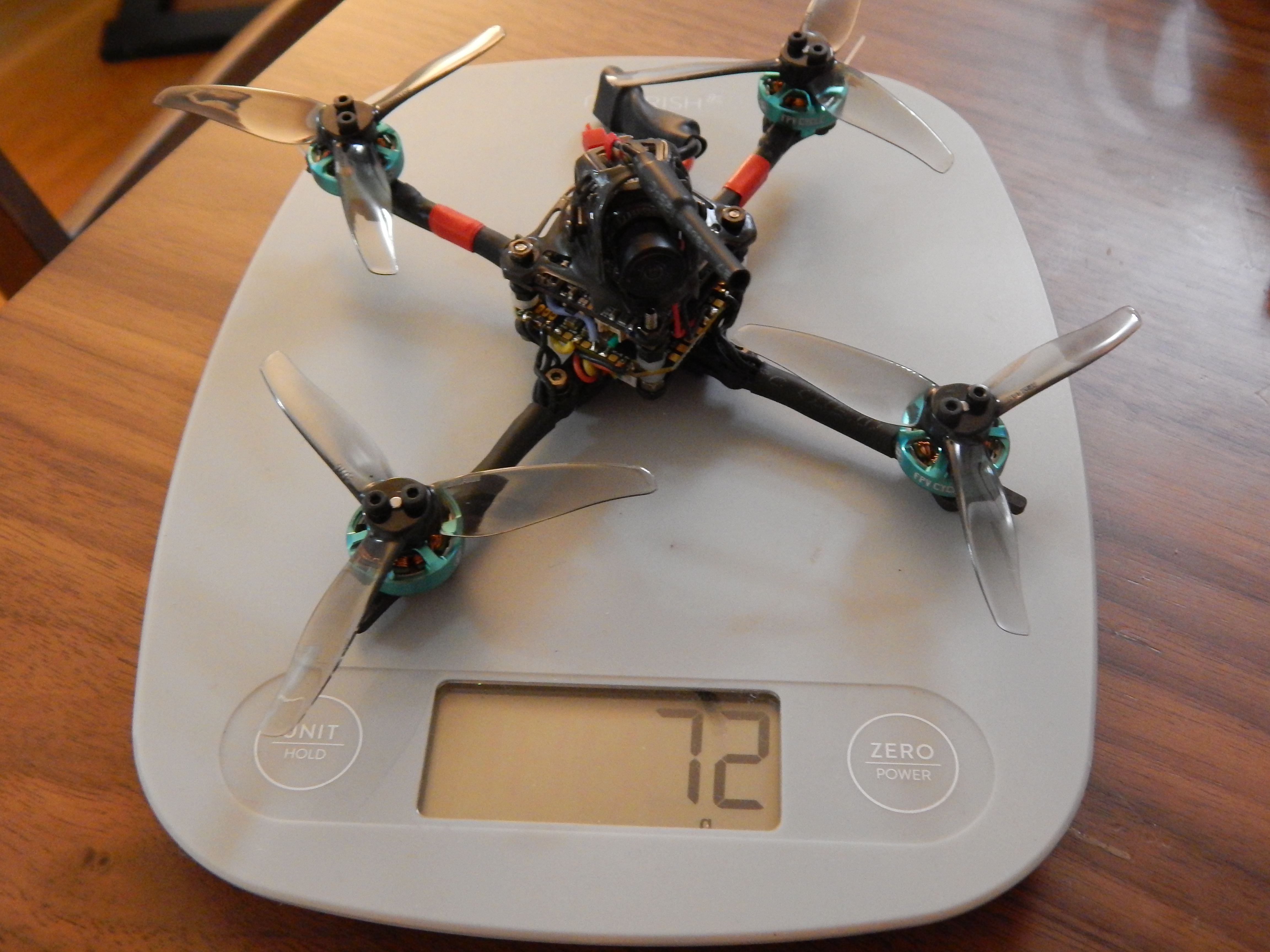
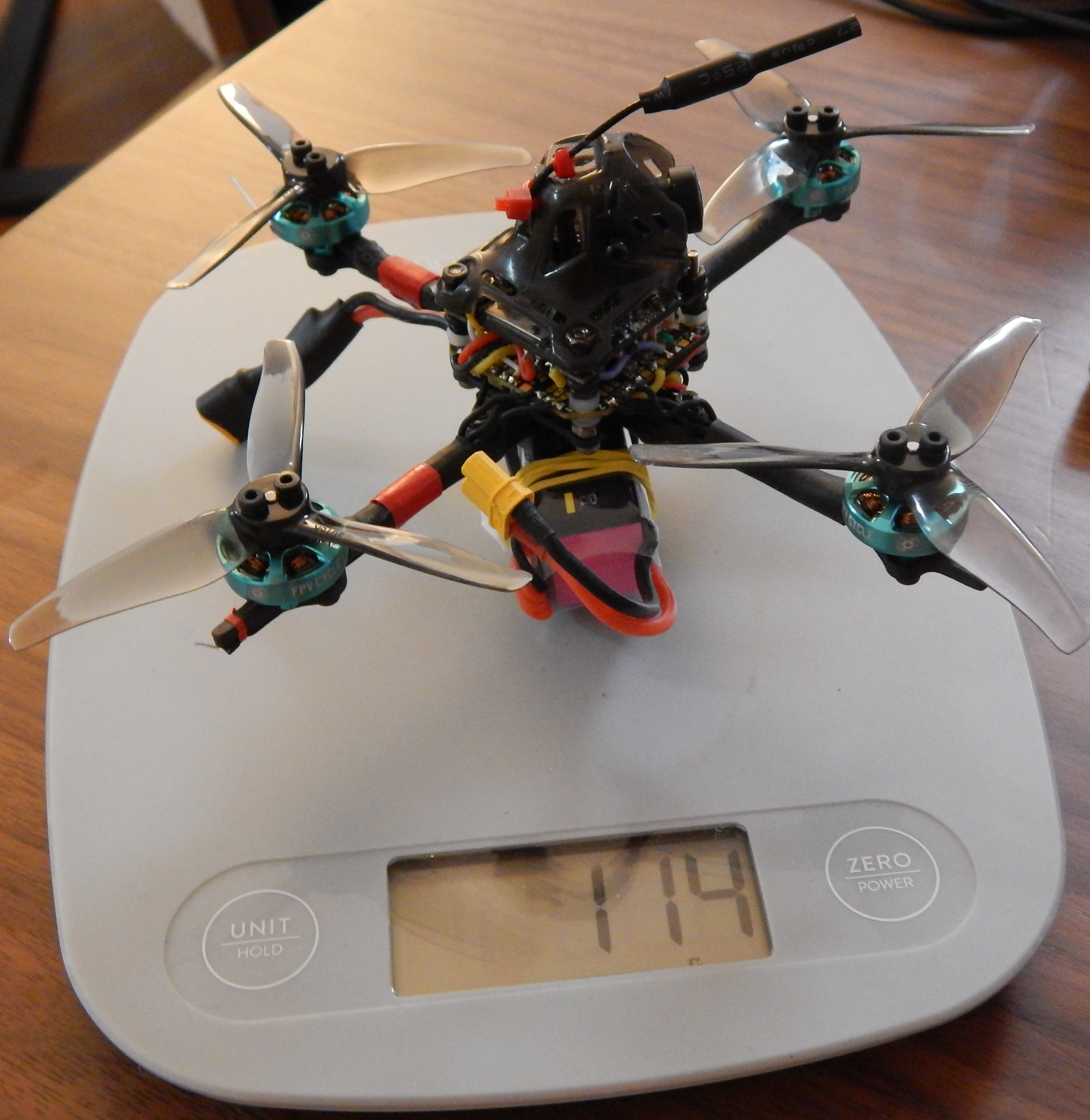
And that’s it! This little guy is ready for its maiden flight. It features a dry weight of 72g, and the battery increases it to 114g. It is a little above the recommended weight for the most efficient performance, but it is a sacrifice I decided to take to add the HD footage. In the next sections I will describe the steps I took to configure the different firmwares (I use Betaflight, BLHeli_S with JazzMaverick and OpenTX), and details on its maiden flight.
The parts I used:
- ToothPick 3 frame (FPVcycle)
- 1303 5000kV 2mm-shaft motors (FPVcycle)
- 3” tri-blade props 3016 – (Gemfan)
- 25mW-400mW 5V VTX (NamelessRC)
- F4 FC+ESC AIO (BeatFPV)
- R-XSR 2.4GHz 16CH ACCST Micro Receiver (FrSky)
- Split 3 Nano whoop camera (RunCam)
- HappyModel Larva X Canopy
- Additional components (excluding tools and soldering aids):
- Silicone Modified Conformal Coating
- Foam tape
- Electrical tape
- Battery pad
- Heat shrink tubing
- 99% Isopropyl Alcohol
- Zip ties
- Elastic rubber bands